Compositionstructure
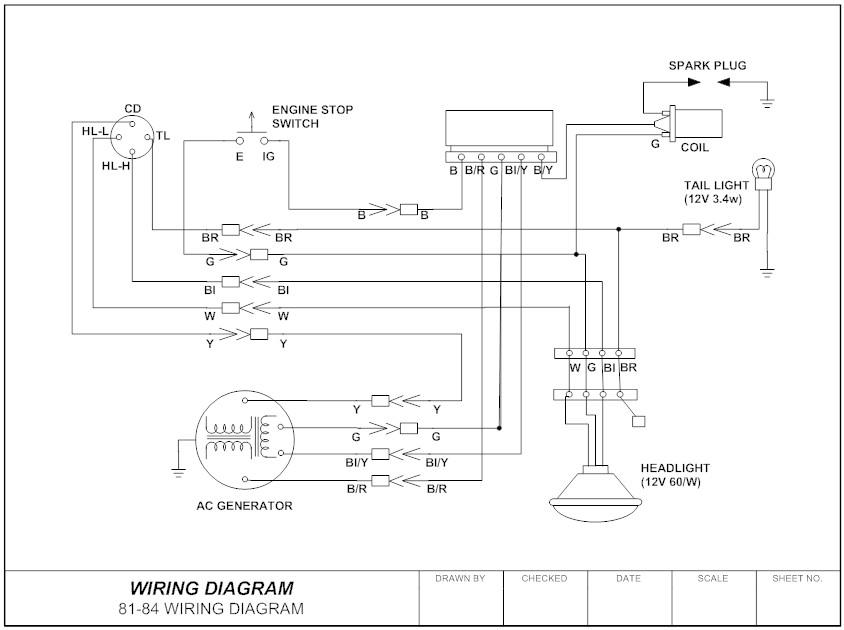
Theelectricalsystemdiagramsmainlyincludeelectricalschematicdiagrams,electricallayoutdiagrams,electricalinstallationwiringdiagrams,etc.ThedrawingsoftwareincludeselectricalCAD,protel99,Cadence,etc.
Therefore,theelectricalschematicdiagramisakindofelectricalsystemdiagram.Itisdrawnaccordingtotheworkingprincipleofthecontrollinediagram,withasimplestructureandclearlevels.Mainlyusedtostudyandanalyzetheworkingprincipleofthecircuit.
Electricallayoutandinstallationdrawingsaremainlyusedtoshowtheactualinstallationpositionsofvariouselectricalequipmentonmechanicalequipmentandintheelectricalcontrolcabinet.Providenecessaryinformationforthemanufacture,installation,maintenanceandrepairofmechanicalandelectricalcontrolequipment.
Electricalinstallationwiringdiagramistoprovidedetailedinformationabouttheelectricalconnectionsbetweeninstallationwiringdiagramitemsforthewiringofdevices,equipmentorcompletesetsofequipment,includingconnectionrelations,cabletypesandlayinglines.
Electricalprincipleiconnote
Commonlymarked:QSknifeswitch,FUfuse,KMcontactor,KAintermediaterelay,KTtimerelay
Electricalappliances,KSspeedrelay,FRthermalrelay,SBbutton,SQtravelswitch.
Componenttechnicaldata
(1)Electricalcomponentlist:componentname,symbol,function,model,quantity,etc.
(2)Useasmallfonttomarkbesidethegraphicsymbolsintheelectricalschematicdiagram.
Commonterminology
Voltagelossandundervoltageprotection:realizedbytheelectromagneticmechanismofthecontactoritself,whenthepowersupplyvoltageisseriouslytooloworlosesvoltage,Thearmatureofthecontactorisreleasedbyitself,andthemotorisshutdownduetopowerloss.
Joggingandlong-moving:Bothendsofthejogbuttonarenotconnectedtothenormallyopencontactsofthecontactorinparallel;bothendsofthelong-movingbuttonareconnectedtothenormallyopencontactsofthecontactorinparallel.
Interlockingcontrol:whenonebranchisenergizedinthecontrolcircuit,theotherbranchisguaranteedtobecutoff.
Doubleinterlock:Doubleinterlockcanbedirectlyswitchedfromonerunningstatetoanotherrunningstate,whichis"forward-reverse-stop".Directstart:Thepowersupplyvoltageisdirectlyaddedtotheterminalofthemotor.Thiscontrolcircuithasasimplestructureandlowcost.Itisonlysuitableforthepracticeofinfrequentstartofthemotorandcannotrealizelong-distanceautomaticcontrol.
Undervoltagestarting:referstotheuseofstartingequipmenttoproperlyreducethevoltageandapplyittothestatorwindingofthemotortostart.Afterthemotorstartsandruns,thevoltageisrestoredtotheratedvaluefornormaloperation.
Maincategories
Electricalcircuitdiagramsincludeschematicdiagrams,blockdiagrams,componentassemblyandsymbolmarkingdiagrams,etc.:
●Schematicdiagram
ElectricalTheschematicdiagramisusedtoshowtheworkingprincipleoftheequipmentandtheroleofthevariouselectricalcomponents.Itisgenerallycomposedofthemaincircuit,thecontrolexecutioncircuit,thedetectionandprotectioncircuit,andthepowerdistributioncircuit.Thiskindofdiagram,becauseitdirectlyembodiestheelectroniccircuitandtheelectricalstructureandthelogicalrelationshipbetweenthem,isgenerallyusedinthedesignandanalysisofcircuits.Whenanalyzingthecircuit,youcanunderstandtheactualworkingconditionsofthecircuitbyidentifyingthevariouscircuitcomponentsymbolsdrawnonthedrawingandtheconnectionbetweenthem.
Theelectricalschematicdiagramcanbedividedintotheprinciplediagramofthewholemachine,theprinciplediagramofthepartialcircuitoftheunit,andtheprinciplediagramofthewholemachinereferstothepartialcircuitdiagramofallthecircuitstogether.
●Blockdiagram(blockdiagram)
Blockdiagramisacircuitdiagramthatusesblocksandconnectionstoshowtheworkingprincipleandcompositionofthecircuit.Toacertainextent,itisalsoakindofschematicdiagram,butinthiskindofdrawing,therearealmostnoothersymbolsexceptforboxesandlines.Themaindifferencebetweenitandtheaboveschematicdiagramisthattheschematicdiagramspecificallydrawsallthecomponentsofthecircuitandtheirconnectionmethods,whiletheblockdiagramsimplydividesthecircuitintoseveralpartsaccordingtothefunction,anddepictseachpart.Toformabox,addsimpletextdescriptionstotheboxes,anduselinesbetweentheboxes(sometimesuselineswitharrows)toillustratetherelationshipbetweentheboxes.Therefore,theblockdiagramcanonlybeusedtoreflectthegeneralworkingprincipleofthecircuit,andtheschematicdiagramcanbeusedasabasisforcollectingcomponentsandmakingcircuitsinadditiontospecificallyshowingtheworkingprincipleofthecircuit.
●Componentassemblyandsymbolmarkdrawing
Itisakindofdrawingusedforcircuitassembly.Thesymbolsonthedrawingareoftenthephysicalshapedrawingofthecircuitcomponent.Thiskindofcircuitdiagramisgenerallyusedforcomparisonbetweentheprincipleandtheactualobject.Theprintedcircuitboardiscoveredwithalayerofmetalfoilonaninsulatingboard,andthenthemetalfoilthatisnotneededbythecircuitiscorroded,andtheremainingpartofthemetalfoilisusedastheconnectionlinebetweenthecircuitcomponents,andthenthecomponentsinthecircuitThedeviceismountedonthisinsulatingboard,andtheremainingconductivemetalfoilontheboardisusedastheconductiveconnectionbetweenthecomponentstocompletethecircuitconnection.Thecomponentassemblydrawingisquitedifferentfromtheschematicdiagram.Itmainlyconsiderswhetherthedistributionandconnectionofallcomponentsarereasonable,andmanyfactorssuchascomponentvolume,heatdissipation,anti-interference,anti-coupling,etc.shouldbeconsidered.Theprintedcircuitboarddesignedbycombiningthesefactorsisdifficulttobecompletelyconsistentwiththeschematicdiagramfromtheoutside.
Electricalinstallationwiringdiagram
Undernormalcircumstances,electricalinstallationdiagramsandschematicdiagramsneedtobeusedtogether.
Themainprinciplesthatshouldbefollowedwhendrawingelectricalinstallationdiagramsareasfollows:
1.Electricalinstallationwiringdiagramsmustbedrawninaccordancewithrelevantnationalstandards.
2.Thepositionandtextsymbolofeachelectricalcomponentmustbeconsistentwiththeannotationsintheelectricalschematicdiagram.Thecomponentsofthesameelectricalcomponent(likethecontacts,coils,etc.ofacontactor)mustbedrawnonAtthesametime,thelocationofeachelectricalcomponentshouldbeconsistentwiththeactualinstallationlocation.
3.Theelectricalconnectionofelectricalcomponentsorsignalsthatarenotonthesamemountingboardorelectricalcabinetshouldgenerallybeconnectedthroughtheterminalblockandconnectedaccordingtothewiringnumberintheelectricalschematicdiagram.
4.Multiplewireswiththesamedirectionandthesamefunctioncanberepresentedbyasinglewireorawireharness.Whendrawingtheconnectingline,thespecification,model,color,numberofwiresandthesizeofthethreadingtubeshouldbemarked.
Electricalcomponentlayoutdrawing
Thedesignofelectricalcomponentlayoutdrawingshouldfollowthefollowingprinciples:
1.MustfollowrelevantcountriesStandarddesignanddrawingoflayoutdrawingsofelectricalcomponents.
2.Whenarrangingthesametypeofelectricalcomponents,thelargerandheavieronesshouldbeinstalledunderthecontrolcabinetorpanel.
3.Heat-generatingcomponentsshouldbeinstalledaboveorbehindthecontrolcabinetorpanel,butthermalrelaysaregenerallyinstalledbelowthecontactortofacilitatetheconnectionwiththemotorandthecontactor.
4.Theelectricalcomponents,operatingswitches,andmonitoringinstrumentsthatneedfrequentmaintenance,adjustmentandoverhaulshouldbeinstalledatasuitableheightforthestafftooperate.
5.Strongcurrentandweakcurrentshouldberoutedseparately,payattentiontotheconnectionoftheshieldinglayertopreventinterferencefromentering.

Thearrangementofelectricalcomponentsshouldconsidertheinstallationgap,andbeasneatandbeautifulaspossible.
Electricalcontrolsystemdiagram
Inordertoexpressthedesignintentofthestructureandprincipleoftheelectricalcontrolsystemoftheproductionmachinery,itisconvenientfortheinstallation,debugging,useandFormaintenance,theelectricalcomponentsandtheirconnectionlinesintheelectricalcontrolsystemareexpressedincertaingraphics.Thisistheelectricalcontrolsystemdiagram.Usewirestoconnectcomponentssuchasmotors,electricalappliances,andmetersaccordingtocertainrequirements,andrealizeacircuitwithspecificcontrolrequirements.
Drawingmethod
Thegeneralrulesfordrawingelectricalschematicdiagramsareasfollows:
Drawthemaincircuit
Whendrawingthemaincircuit,themaincontrol,protectionandotherelectricalequipment,suchascircuitbreakers,fuses,inverters,thermalrelays,motors,etc.,shouldbedrawnwiththicksolidlinesinaccordancewiththespecifiedelectricalgraphicsymbols,andMarktherelevanttextsymbolsinturn.
Drawingcontrolcircuit
Thecontrolcircuitisgenerallycomposedofswitches,buttons,signalindicators,contactors,relaycoilsandvariousauxiliarycontacts.Simpleorcomplexcontrolcircuitsaregenerallycomposedofvarioustypicalcircuits(suchasdelaycircuits,interlockcircuits,sequencecontrolcircuits,etc.)tocontrolthe"start"and"start"ofthecontrolledequipmentinthemaincircuit."Run"and"Stop"maketheequipmentinthemaincircuitworknormallyaccordingtotherequirementsofthedesignprocess.Forasimplecontrolcircuit:aslongasitisbasedonthefunctionstoberealizedbythemaincircuit,combinedwiththeproductionprocessrequirementsandthefirstandlastorderofequipmentactions,analyzeanddrawcarefully.Forcomplexcontrolcircuits,dividethemintoseveralpartialcontrolcircuitsaccordingtothefunctionscompletedbyeachpart,andthencomparethemwithtypicalcircuitstofindoutthesimilarities,andfollowtheprincipleofsimplifyingfirst,thencomplicated,andeasyfirstandthendifficultonebyone.Draweachpartofthelink,andthenfindtherelationshipbetweeneachlink.
Drawingprinciples
1.Accordingtotheelectricalsymbolstandard---drawaccordingtotheelectricalsymbolspecifiedbythenationalstandard.
2.Standardsfortextsymbols---indicatedinaccordancewiththetextsymbolsspecifiedinthenationalstandardGB7159-1987.
3.Arrangeinorder---Arrangeverticallyorhorizontallyaccordingtotheworkingorder.
4.Usetheunfoldingmethodtodrawthemaincircuitinthecircuit,withathicksolidlinedrawnontheleft,upperorlowerpartofthedrawing.
5.Indicatetheprincipleofactionandtherelationshipbetweencontrol---Therelationshipbetweencontrolandbeingcontrolledmustbeclearlyexpressed.
6. Maincircuitandauxiliarycircuit(maincircuit,auxiliarycircuit)intheelectricalschematicdiagram.
Identificationmethod
Thegeneralwaytolookattheelectricalcontrolcircuitdiagramistolookatthemaincircuitfirst,thentheauxiliarycircuit,andusetheauxiliarycircuitlooptostudythecontrolprogramofthemaincircuit.
1.Stepstoseethemaincircuit
Thefirststep:seeclearlytheelectricalequipmentinthemaincircuit.Electricalequipmentreferstoelectricalappliancesorelectricalequipmentthatconsumeelectricalenergy.Thefirstthingtolookatthepictureistoseeclearlyhowmanyelectricalappliancesareused,theircategories,uses,wiringmethods,andsomedifferentrequirements.
Step2:Tofigureoutwhatelectricalcomponentsareusedtocontroltheelectricalequipment.Therearemanywaystocontrolelectricalequipment,somearedirectlycontrolledbyswitches,somearecontrolledbyvariousstarters,andsomearecontrolledbycontactors.
Step3:Understandthecontrolappliancesandprotectionappliancesusedinthemaincircuit.Theformerreferstocontrolcomponentsotherthanconventionalcontactors,suchaspowerswitches(transferswitchesandaircircuitbreakers)anduniversaltransferswitches.Thelatterreferstoshort-circuitprotectiondevicesandoverloadprotectiondevices,suchasthespecificationsofelectromagnetictripsandthermaloverloadtripsinaircircuitbreakers,andtheusesandspecificationsofcomponentssuchasfuses,thermalrelaysandovercurrentrelays.Generallyspeaking,aftertheaboveanalysisofthemaincircuit,theauxiliarycircuitcanbeanalyzed.
Step4:Lookatthepowersupply.Itisnecessarytounderstandthepowersupplyvoltagelevel,whetheritis380Vor220V,whetheritissuppliedfromthebusbarorthedistributionpanel,orisconnectedfromthegeneratorset.
2.Seethestepsoftheauxiliarycircuit
Theauxiliarycircuitincludesacontrolcircuit,asignalcircuitandalightingcircuit.
Analyzethecontrolcircuit.Accordingtothecontrolrequirementsofthemotorsandexecutiveappliancesinthemaincircuit,findouttheothercontrollinksinthecontrolcircuitonebyone,"smashthecontrolcircuitintozero",anddivideitintoseverallocalcontrolcircuitsforanalysisaccordingtodifferentfunctions.Ifthecontrolcircuitismorecomplicated,youcaneliminatethecircuitsthatarenotcloselyrelatedtothecontrol,suchaslighting,display,etc.,inordertoconcentrateontheanalysis.
Thefirststep:lookatthepowersupply.Firstlookatthetypeofpowersupply.IsitACorDC?Secondly.Itisnecessarytoseewherethepoweroftheauxiliarycircuitisconnectedanditsvoltagelevel.Thepowersupplyisgenerallyconnectedfromthetwophasewiresofthemaincircuit,anditsvoltageis380V.Itisalsoconnectedfromaphaselineandazerolineofthemaincircuit,thevoltageissingle-phase220V;inaddition,itcanalsobeconnectedfromadedicatedisolationpowertransformer,thevoltageis140,127,36,6.3V,etc.WhentheauxiliarycircuitisDC,theDCpowersupplycanbeconnectedfromtherectifier,generatorsetoramplifier,anditsvoltageisgenerally24,12,6,4.5,3V,etc.Theratedvoltageofthecoilofallelectricalcomponentsintheauxiliarycircuitmustbeconsistentwiththevoltageoftheauxiliarycircuitpowersupply.Otherwise,thecircuitcomponentswillnotoperatewhenthevoltageislow;whenthevoltageishigh,thecoilsoftheelectricalcomponentswillbeburnedout.
Step2:Understandthepurposeofvariousrelaysandcontactorsusedinthecontrolcircuit,suchassomespecialstructurerelays,andunderstandtheiroperatingprinciples.
Step3:Studytheactionofthemaincircuitaccordingtotheauxiliarycircuit.
Analyzetheabovecontentandcombinetherequirementsinthemaincircuittoanalyzetheactionprocessoftheauxiliarycircuit.
Thecontrolcircuitisalwaysdrawnbetweentwohorizontalpowerlinesortwoverticalpowerlinesintheorderofaction.Therefore,itcanbeanalyzedfromlefttorightortoptobottom.Forcomplexauxiliarycircuits,theentireauxiliarycircuitinthecircuitconstitutesalargeloop,whichisdividedintoseveralindependentsmallloops,andeachsmallloopcontrolsanelectricalapplianceoranaction.Whenasmallloopformsaclosedloopandcurrentflowsthroughit,theelectricalcomponents(contactorsorrelays)intheloopwillacttoconnectelectricalequipmenttopeopleorcutoffthepowersupply.Intheauxiliarycircuit,thecircuitisusuallyconnectedbyabuttonorachange-overswitch.Theanalysisofthecontrolcircuitmustbecarriedoutinconjunctionwiththeactionrequirementsofthemaincircuitatanytime.Onlyafteracomprehensiveunderstandingoftherequirementsofthemaincircuitonthecontrolcircuitcanyoutrulygrasptheactionprincipleofthecontrolcircuit.Theactionprincipleofeachpartshouldnotbeviewedinisolation,butattentionshouldbepaid.Whetherthereisamutualrestrictionbetweenvariousactions,suchasinterlockingbetweentheforwardandreverserotationofthemotor.
Step4:Studytherelationshipbetweenelectricalcomponents.Allelectricalcomponentsinthecircuitdonotexistinisolation,butareinterrelatedandrestricteachother.Thismutualcontrolrelationshipissometimesmanifestedinoneloop,andsometimesinseveralloops.
Step5:Researchotherelectricalequipmentandelectricalcomponents.Suchasrectifierequipment,lightinglamps,etc.
Operationsteps
1.Theelectricalschematicdiagramisgenerallydividedintotwoparts:themaincircuitandtheauxiliarycircuit.
2.Allcomponentsinthefigureshouldadoptthegraphicsymbolsandtextsymbolsuniformlystipulatedinthenationalstandards.
3.Layout.
4.Textsymbollabeling.
5.Graphicsymbolsindicatethemainpoints:nopowerornoexternalforcestate.
6.Linecrossingandgraphicdirection.
7.Figureareaandindex.
Maincircuit:Itisthepartoftheelectricalcontrolcircuitthroughwhichlargecurrentpasses,includingtheelectricalcomponentsconnectedfromthepowersupplytothemotor;generallyconsistsofacombinationswitch,mainfuse,maincontactofcontactor,andthermalrelayThethermalelementandtheelectricmotorarecomposed.
Auxiliarycircuit:Itisacircuitotherthanthemaincircuitinthecontrolcircuit,andthecurrentflowingthroughitisrelativelysmall.Theauxiliarycircuitincludesacontrolcircuit,alightingcircuit,asignalcircuitandaprotectioncircuit.Thecontrolcircuitiscomposedofbuttons,contactorsandrelaycoilsandauxiliarycontacts,thermalrelaycontacts,andprotectiveelectricalcontacts.
Technicalparameters
Graphicsandtextsymbols
Nationalstandardsforelectricalgraphicsymbolsandtextsymbols
ThegraphicsymbolsarebasicallyuniformNationalstandards
ShouldbedrawnaccordingtothestandardsspecifiedinGB4728-85,GBTl59-87,GB6988-86,etc.
